After seeing the video What’s the big circle on my wall? by Make Anything about his double pendulum I was immediately fascinated by the pattern that it generated and I wanted to build this myself. He also made a 1-hour version with the pendulum swinging, but he had to start the movement again and again by hand and it was clearly visible how the pendulum lost momentum.
That’s when I thought: I can do that better!
At first, I had the idea of using an electromagnet somewhere in the board to attract an iron weight. This would have needed good timing and a strong electromagnet to overcome the distance to the moving part. Then I thought maybe put the whole magnet-iron attraction mechanism behind the board and just bring the movement to the back with a shaft attached to the first beam.
Then I realized that what I need is basically just a motor with low friction. The first version of my double pendulum actually just had a brushed DC motor with no gearing. And it worked great! However the motor was basically constantly stalled which wasn’t good for the brushes even though I did incorporate a current limit via the motor driver IC.
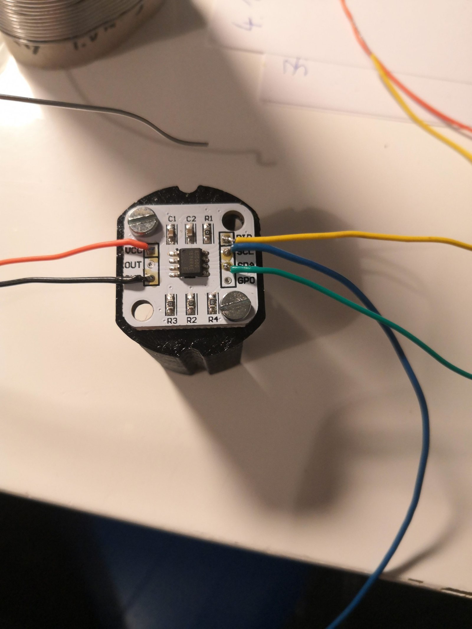
That’s when I decided to go full on overengineering-mode and built a double pendulum with a motor in each of the axis. I found BLDC motors that are normally used for gimbals. They can be positioned fairly exactly, can hold a position and are backdrivable which basically means the motor can be manipulated by moving the output with an external force. They also usually have a hollow shaft so cables can be passed through the rotating assembly with the help of a slip ring. However, they need some position feedback to be able to do all this. I decided to go for the magnetic position sensor AS5600. A magnet ring gets attached to the back of the motor and opposite of that is the sensor. That way the cables can still pass through. But the assembly gets relatively complex.


Another big obstacle for me was the programming side of things because these motors require some advanced control in order to work at all. After making my first couple of tries and letting the whole project rest for a year I was lucky enough that the great Antun Skuric had started to work on his Open Source Arduino Library SimpleFOC which was exactly what I needed! I was really impressed by all the people that helped with the code and I cannot thank them enough for sharing their knowledge and putting so much effort into it!
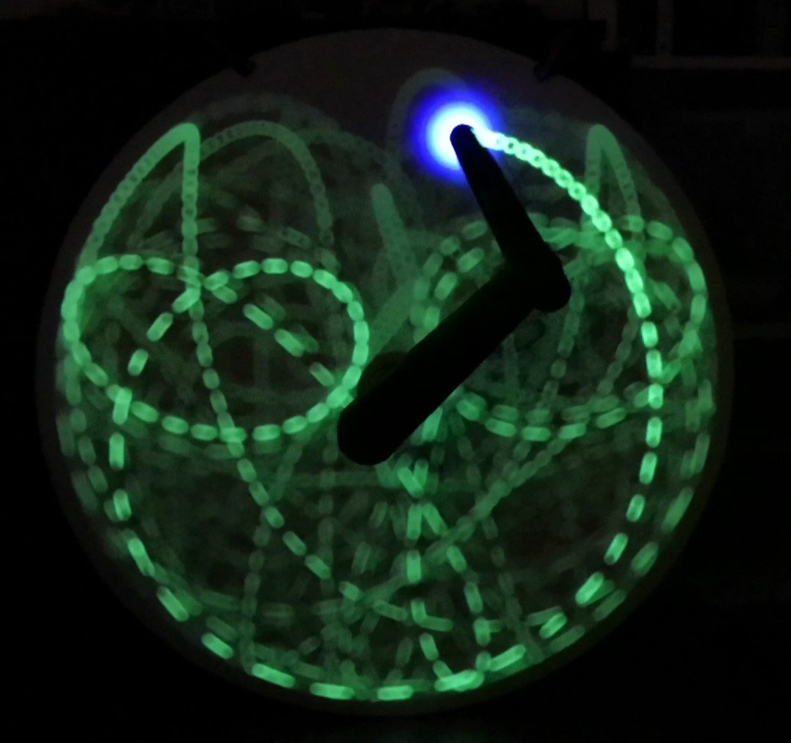
I had some major problems with the electrical connections through the slip ring to the second magnet sensor. There was probably some interference between the data signals of the sensor and the power lines to the motor so the data was just not clean enough to work. That is why I was never able to move the pendulum in a completely deterministic manner. Only the chaotic mode was possible. Nevertheless, it looks really great and the extra bright 3 Watt LED was also quite effective.
Here is a longer version. On top of the chaotic nature of the pendulum, I let the program change the applied torque randomly. At some points in the video, I would wish for a bit more chaos, but I think that is because the not functional second motor dampens the movement too much.